This is an area that often causes struggle so this should explain everything about transient throttle correction on Adaptronic ECUs. There are two reasons why we need it.
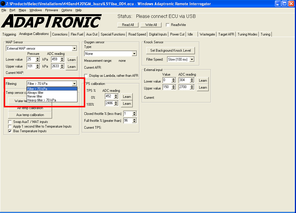
The first is that on an engine tuned with a MAP sensor (also called speed density), the ECU has to do filtering on the MAP sensor signal to get a smooth enough signal to use for tuning purposes. This filtering slows down the response of the sensor. So when you snap open the throttle, the MAP reading that the ECU sees doesn’t change straight away. However the air demand of the engine does change straight away, because the pressure wave travelling through the throttle to the intake ports moves at the speed of sound, so the engine had better get that extra fuel straight away.
To pick some numbers out of the air, an engine might idle at around 33 kPa. When you snap open the throttle from idle, the manifold pressure will go pretty much to 100 kPa in a matter of milliseconds, but the MAP sensor reading will slowly go up to 100 kPa over a period of a few hundreds of milliseconds. If you were trying to get the correct amount of fuel into the engine by providing an enrichment, then you’d need to enrich by about 200% to get the correct fuel for 100 kPa in when the ECU is still seeing 33 kPa from the sensor. We don’t like to do this because it’s a kludge; it doesn’t really represent what’s happening on the engine and working out that percentage for different throttle openings and RPM would be a big task.
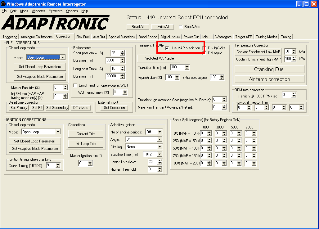
So the way we do it instead is with a technique we call “MAP prediction”. It’s really simple. When the ECU sees a quick throttle movement, the ECU looks at the predicted MAP table instead of the MAP sensor, for a fixed duration. Once that duration is up, it goes back to looking at the value from the MAP sensor. During this time, the ECU actually picks whichever is greater out of the two (the MAP sensor and the predicted MAP value) so that if you’re on boost and nail the throttle the last few percent, the ECU won’t reduce the amount of fuel.
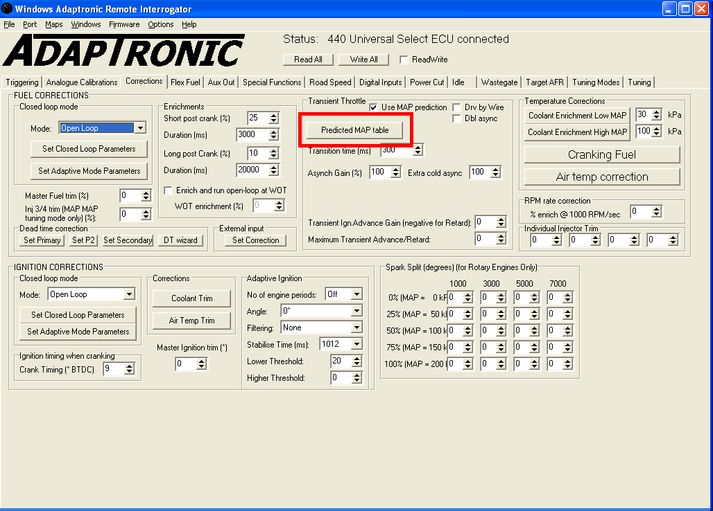
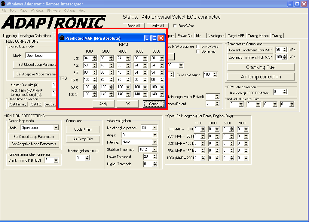
To set it up, you just need to go to the different RPM and throttle position points and enter into the predicted MAP table the actual MAP value that you see. The duration depends on how much filtering you’re using, how long your MAP sensor hose is and so on but generally values in the range of 150 – 300 ms work well.
One word of warning, if your values in the table are too high, then you will see jumps in the MAP reading in the log file at what you think is constant throttle. The ECU will react to very small changes in the throttle and start to look at the predicted MAP table, so if the values in the table are too high, you’ll get a jump in the MAP reading for that period of time. The way to fix this is to set the predicted MAP values.
The second reason we need correction for transient throttle is actually two separate reasons. The first relates to the first intake stroke during or shortly after opening the throttle. If you imagine that you inject the fuel just before the intake valve opens, then during the intake stroke is when the driver opens the throttle. The amount of air that goes into the cylinder will be way more than what the ECU used to calculate the fuel dose when the throttle was closed. So in this case we have to give an additional squirt on the injector, not timed with the intake valve, but timed with the throttle opening. We call this an asynchronous pulse, because it’s not synchronised to engine rotation.
Another reason we need this asynchronous burst is that we get fuel pooling in the intake. The fuel comes out of the injector as a mist and some if it condenses and collects on the intake runner walls. The longer the time between the injector squirt and the intake stroke, the more fuel condenses. So it should be obvious that getting the injector phasing / timing correct helps a lot with throttle response. Also, the colder the intake system, the faster the fuel condenses.
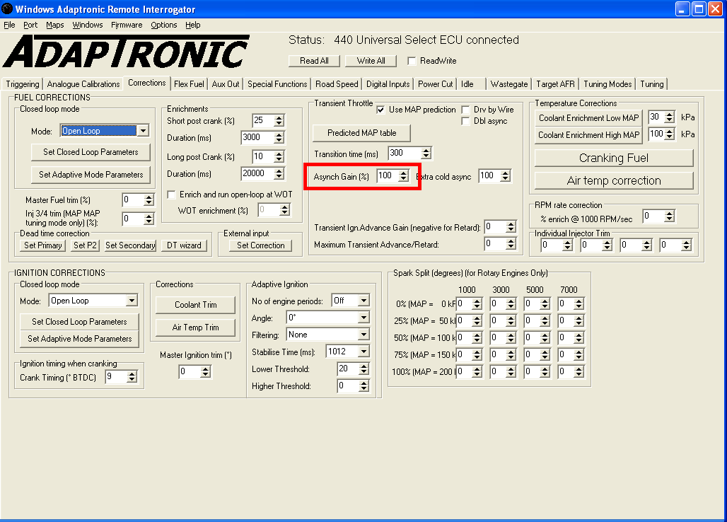
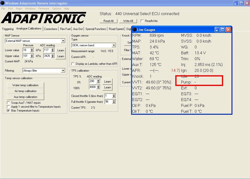
To deal with this, the ECU monitors for changes in the fuel millisecond pulse. When it sees a change of more than 2 ms, it generates a pulse equal to the difference, multiplied by a gain which we call the asynchronous gain. For example if we’re idling at 2 ms of injector duration, and we suddenly open the throttle and the engine wants 7 ms, then the ECU will detect a difference of 5 ms. If our asynchronous gain is set to 150%, then the ECU will generate an asynchronous injector burst of 7.5 ms. You can see this on the “Pump” field in the gauges window, and in the log file.
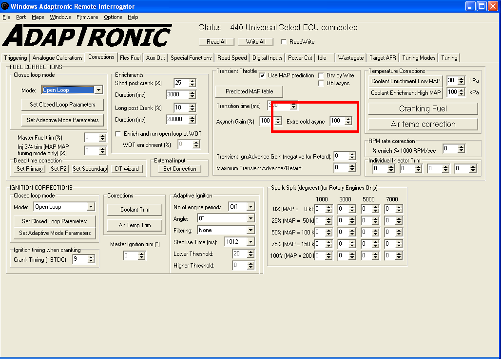
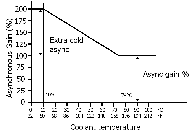
I mentioned before that the colder the intake system is, the more asynchronous pump we need. To compensate for this, we have an additional amount for when the engine is cold. This is applied at 10 degrees C or 50 degrees F, and tapers off up to 74 degrees C or 165 degrees F. A good starting point for a sequentially injected engine is about 100% of async, with an additional 100% when cold.
You’ll know if the async gain is too high because the engine will feel “jolty” when you apply the throttle. You’ll know if it’s too low because you’ll get a lean miss when you open the throttle.
One further word of something to look out for is if you’re getting the “pump” happening at constant throttle, check the log file. If it shows the MAP reading jumping around a lot, then that’s an indication that you need a better MAP pickup location.
For example, right after the throttle body is not a good location due to turbulence. If you can’t get a better MAP sensor location, then you can increase the filtering setting for the MAP sensor.